Transformer
M/s. GMDT Marine & Industrial Engineering Pvt. Ltd offer the Transfromer for the Marine and Industrial segment. Brief on the same has been depicted as follow:
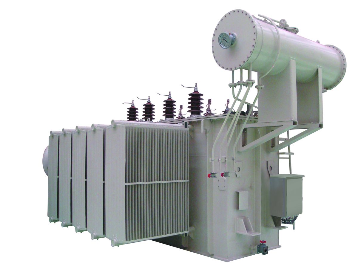
A) Power transformers
M/s GMDT Marine & Industrial Engineering Pvt. Ltd offers power transformers which are key components in power networks. Their availability and longevity have a major impact on grid reliability and profitability. GMDT does not compromise on quality. We ensure that every one of our delivered units has undergone rigorous full-acceptance testing. GMDT offers a complete range of power transformers and related components and parts.
Our entire range is the result of our own research, development and manufacturing, which makes us unique in the industry. This has given us extensive experience in every relevant part of power transformer technology. Customers worldwide can securely rely on the quality and reliability of our products.
Applicable Standards
IEC / ANSI /BS / IS / SABS/ CENELEC /GOST/ JIS/DIN

Salient Features
- Pioneering technology – best short circuit record in the industry
- Industry leading ‘Mean time between failure rate (MTBF)’
- The complete customer service package (from quotation to Commissioning)
- Short circuit performance at twice the industry standard
- One global approach - bringing consistency, delivery performance and technology
- Compact design to meet transportation limits, including the possibility of lay down transportation.
- Exceptional mechanical robustness and natural ability to withstand short circuit events and transportation accelerations.
- As the technology pioneer, GMDT has the flexibility to electrically and mechanically match existing units that make it the best option for replacement of transformers, meeting dimensional and connection arrangements and impedance requirements, even those with low impedances, high impedances to tertiary winding and lay-down operation.
- Available in Stack core
- Modern manufacturing techniques ensuring quality of product
- Robust build designed to withstand electric impulses, thermal and dynamic stress
- Trouble free performance
- Customized design and specification demands
- GMDT’s patented concept
- Customized solution to meet every contingency
- Proven track record in meeting customer performance requirements.
- Design technology eliminates the risk of a hot spot
- Outstanding thermal performance resulting from directed oil flow, minimization of losses and control of the hot spot
We offers following Power transformers
- Generator step-up transformers (GSU)
- HVDC converter transformers
- Shell specialty transformers
- System intertie transformers
- Unit Auxiliary Transformer
- Station Auxiliary Transformer
- Interconnecting Transformer (Auto Transformer)
- Trackside Transformer for Railways
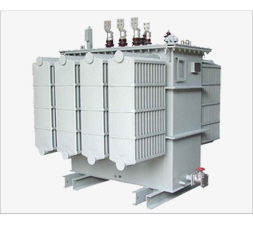
B) Distribution Transformers
M/s. GMDT Marine & Industrial Engineering Pvt Ltd. offers a wide range of distribution and medium power transformers for Marine and industrial application. These transformers can be free breathing or hermetically sealed. Conventional transformers are fitted with a conservator with breather for free breathing while hermetically sealed are without breathing with bolted cover. Wide range of transformers in accordance to respective standards with different combinations can be constructed.
Distribution transformers for Marine and industrial application is available in 3 or 1 phase version with appropriate primary and secondary voltages. We offers single phase distribution transformers, three phase distribution transformers and industrial distribution transformers.
These single phase distribution transformers and three phase distribution transformers are available with 'Tap Changer' options as well as "Off Circuit Manually Operated" and "On Load Tap Changer" (OLTC) with AVR and RTCC panel.
Three Phase Distribution Transformers
Distribution transformers are normally located at a service drop, wires run from a utility pole or underground power lines to a customer's premises. They are often used for the power supply of facilities outside settlements, such as isolated houses, farmyards or pumping stations at relevant voltages.
M/s. GMDT Marine & Industrial Engineering Pvt. Ltd makes three phase distribution transformers are available in stack core / wound core. They are made available in aluminium / copper as per requirement.
Single Phase Distribution Transformers
At GMDT Marine & Industrial Engineering Pvt. Ltd, we offer single phase transformers in CRGO Steel core as well as Amorphous Metal core in line with the client requirement. Single-phase distribution transformers are widely used by utilities to provide 24hour electricity supply in rural areas.
We are in a position to offer any specially designed voltage distribution transformers for special purposes as per customer’s requirements and specifications. Due to the versatile design, unmatched quality and unquestionable performance, these distribution transformers are widely demanded in the market.
Prime quality, low loss, high permeability "Cold Rolled Grain Oriented" silicon steel is used for core to achieve low no load losses.
These industrial distribution transformers have electrolytic copper with insulating paper multi covered round wires and strips are used for both the primary and secondary windings to achieve low load losses.
Copper foil winding technology is used for high current sections to achieve following advantages:
- Sustaining short circuit forces without any distortion in low voltage and high current windings
- Hot spot in LV windings regulated
- No transposition, stray losses are minimal. Thus total copper losses are also further reduced
- Total copper losses reduced vis-a-vis standard losses. Thus heat dissipating area also reduces
ONAN cooling with conventional pressed steel radiators or corrugated walls are provided for special Transformers ONAF cooling with fans for specific requirement. The terminal of these single phase distribution transformers and three phase distribution transformers arrangement for primary and secondary voltage are decided as per site requirements. Low viscosity transformer oil is provided with in numerous superior grades for specific usage
Applicable standards
IEC / ANSI /BS / IS / SABS/ CENELEC / GOST
Salient Features
- Hermitically Sealed and Conservator type of construction
- Robust design to take care of frequent short circuits
- Excellent process of shrinkage and drying of coils resulting in a sturdy construction
- Manufactured with prime CRGO using step-lap design for low losses
- Stepdown Transformers
- Stepup Transformers
- Energy Efficient Tranformers
- Transformers ment for Solar and Wind Applications
- Transformers ment for Mines Applications
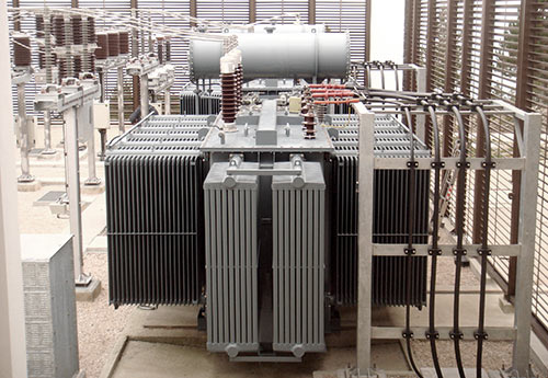
C) Furnace Transformers
We offer furnace transformers and arc furnace transformers for arc furnace/ submerged arc furnace/ induction furnace applications.
In the furnace transformers, we use superlative materials that make the transformer highly durable and resistive to various climatic factors. The customers are facilitated to place the orders according to the requirement as the transformers are available in different current transforming capacities. Low maintenance, unmatched quality and unquestionable performance has made the arc furnace transformers highly demanded in the national as well as in the international market.
Electric Arc Furnace (EAF) Transformers are required for many different furnace processes and applications. They are built for steel furnace, ladle furnace and ferroalloy furnace, and are similar to short or submerged Arc Furnace Transformers.
EAF Transformers operate under very severe conditions with regard to frequent over currents and over voltages generated by short circuits in the furnace and the operating of HV circuit-breaker.
Transformers for alternating current electric-arc furnaces (AC EAFs) are utilised throughout the steel industry. They are used to power arc furnaces for the production of steel, which require high levels of power that must also be variable due to the frequent short-circuits, and also to power arc furnaces for the production of special alloys – these alloys often require the deployment of three single-phase furnace transformers instead of a single three-phase transformer.
These transformers must be designed to resist the high levels of electrical, thermal and mechanical stress to which they are subject during utilisation.
Other elements that must be taken into consideration when designing transformers for electric-arc furnaces are the high secondary currents required for the fusion process (dozens of kA) and the wide range of secondary voltages, which are normally regulated by an on-load tap changer (OLTC), either directly on the high-voltage winding or via an intermediate booster located within the same tank.
An additional option that is now often used in furnace transformers is the closure of the secondary electrical circuit (triangle) within the transformer tank. Furnace transformers are often used in series with an on-load tap changer (OLTC) or a no-load tap changer (NLTC), which serves to enhance the stability of the arc. The reactor can be built inside the main transformer cabinet, or alternatively, it can be entirely separate from it or located next to it.
This solution makes it possible to eliminate the costs of cabling the MV connections between the transformer and the reactor, thus making it possible to carry out maintenance work on the reactor without having to shut off the transformer. In this way, the overall reliability of the system can be enhanced.
The experience that GMDT has built up has allowed to company to become a leading brand both nationally and internationally in the furnace transformers market. The company’s products are used across a wide spectrum of applications by a plethora of major clients.
Applicable standards
IEC / ANSI /BS / IS / SABS/ CENELEC / GOST
Specifications
- "Off Circuit Manually Operated" and "On Load Tap Changer" (OLTC) with AVR and RTCC panel
- OFWF cooling with ONAN cooling optional
- ONAN cooling with conventional pressed steel radiators
- Requisite series reactors for arc furnace transformers to reduce the short circuit stresses generated in transformer during the furnace operation
- Designed to withstand the harmonics generated due to furnace operation
- 'Tap Changer' options available in these furnace transformers, arc furnace transformers and electric arc furnace transformers.
Design options of Electric Arc Furnace (EAF) Transformers
- Direct or indirect regulation
- On-load or off-circuit tap changer
- Built-in reactor for long arc stability
- Air or water-cooled secondary bushing arrangements and designs
- Internal secondary phase closure (internal delta)
Furnace Transformer
- Arc Furnace Transformer
- Submerged Arc Furnace Transformer
- Ladle Furnace Transformer
- Induction Furnace Transformer
- DC Arc Furnace Transformer
Salient Features
- Industry leading ‘Mean time between failure rate (MTBF)’
- The complete customer service package (from quotation to Commissioning)
- One global approach - bringing consistency, delivery performance and technology
- Compact design to meet transportation limits, including the possibility of lay down transportation.
- Modern manufacturing techniques ensuring quality of product
- Robust build designed to withstand electric impulses, thermal and dynamic stress
- Trouble free performance
- Customized design and specification demands
- Customized solution to meet every contingency
- Design technology eliminates the risk of a hot spot
- Outstanding thermal performance resulting from directed oil flow, minimization of losses and control of the hot spot
- Robust design to take care of frequent short circuits
- Excellent process of shrinkage and drying of coils resulting in a sturdy construction
D) Earthing Transformers
An earthing transformer is usually associated with three-phase supply systems.
On a three-phase system, the neutral would be earthed either directly or through some limiting impedance / resistance. When the neutral point is not available or does not exist with a delta secondary winding of the transformer, a neutral point needs to be created. This is the purpose of the earthing transformer, which could consist of a zig- zag winding, or a two-winding star delta transformer where the star winding of correct voltage supplies an accessible neutral point when connected to the supply system.
Earthing transformers are classified as standard reactors. An earthing transformer (neutral coupler) is a three-phase transformer connected to the power system to provide a neutral connection for earthing, either directly or via impedance. The earthing transformers may in addition supply a local auxiliary load.
The earthing transformer creates a neutral point for a network. ZN connection is usually applied. Z connection provides linear and specified zero sequence impedance. YN+d can also be applied.
A Earthing ( zigzag ) transformer is a special purpose transformer with a zigzag or 'interconnected star' winding connection, such that each output is the vector sum of two phases offset by 120°.
Its applications are for the creation of a missing neutral connection from an un-grounded, 3-phase system to permit the grounding of that neutral to an earth reference point and also harmonic mitigation, as it can suppress triplet (3rd, 9th, 15th, 21st, etc.) harmonic currents, to supply 3-phase power as an auto transformer (serving as the primary and secondary with no isolated circuits), and to supply non-standard phase-shifted 3-phase power.
Nine-winding three-phase transformers, typically have 3 primaries and six identical secondary windings which be used in zigzag winding connection. As with the conventional delta or wye winding configuration three-phase transformer, a standard stand-alone transformer containing only six windings on three cores can also be used in zigzag winding connection, such transformer sometimes being referred to as a zigzag bank. In all cases, six or nine winding, the first coil on each zigzag winding core is connected contrariwise to the second coil on the next core. The second coils are then all tied together to form the neutral and the phases are connected to the primary coils. Each phase, therefore, couples with each other phase and the voltages cancel out. As such, there would be negligible current through the neutral point, which can be tied to ground.
Each of the three "limbs" are split into two sections. The two halves of each limb have the equal number of turns and they're wound in opposite directions. With the neutral grounded, during a phase to ground short fault, a third of current returns to the fault current and the remainder must go through two of the three phases when used to derive a grounding point from a delta source.
If one phase, or more, faults to earth, the voltage applied to each phase of the transformer is no longer in balance; fluxes in the windings no longer oppose. (Using symmetrical components, this is Ia0 = Ib0 = Ic0.) Zero sequence (earth fault) current exists between the transformer’s neutral to the faulting phase. The purpose of a zigzag transformer in this application is to provide a return path for earth faults on delta-connected systems. With negligible current in the neutral under normal conditions, providing the defective load will be automatically disconnected in a fault condition, an undersized transformer may be used only as short time rating is required (i.e. the transformer can only carry full rated current for, say, 60 s). Impedance should not be too low for desired maximum fault current. Impedance can be added after the secondaries are summed to limit maximum fault currents.
Applicable standards
IEC / ANSI /BS / IS / SABS/ CENELEC / GOST
Application in following industries
Chemical, Pharmaceuticals, Steel, Textile, Engineering, Plastic, Cement, Refineries, Mining, Captive Power Projects, Hydro Power Projects, Wind Mill Farms, Construction Houses, Pharma, Electrical, Electronics, Renewable Energy, Automobile.
Salient Features
- Optimized design fully in line with substation system design
- Lots of references in different voltage systems and substation configurations
- Respectful with people and property
- Powerful engineering and GMDT design
- Customized solutions for all customers
E) Rectifier Transformers
Rectifier transformers are different from normal power and distribution transformers because they are special transformers made for industrial application. A Rectifier transformer is a special application transformer which includes diodes and thyristors in the same tank.
Power electronic circuits can convert alternating current (ac) to direct current (dc). These are called rectifier circuits. Power electronic circuits can also convert direct current to alternating current. These are called inverter circuits. Both of these circuits are considered to be converters.
A transformer that has one of its windings connected to one of these circuits, as a dedicated transformer, is a rectifier transformer or converter transformer.
Some other special industrial purpose transformers are Electric arc furnace transformers (EAF), DC electric arc furnace transformers (DC EAF), Rectifier transformers, Converter transformers, Line Feeders.

Applicable standards
IEC / ANSI /BS / IS / SABS/ CENELEC / GOST
Where Rectifier Transformers are Used?
Rectifier transformers are used for industrial processes which require a significant direct current (dc) supply. Rectifier circuits are used to provide high-current dc for electrochemical processes like chlorine production as well as copper and aluminum production.
They are also used in variable-speed-drive motor controls, transit traction applications, mining applications, electric furnace applications, higher-voltage laboratory-type experiments, high-voltage direct-current power transmission (HVDC), static precipitators, and others.
Operation of Rectifier Transformers
Rectifier transformers can be liquid-immersed, dry-type, or cast-coil technology. Dry type transformers were primarily used in distribution-voltage classes. Dry type and cast coil — are limited by voltage and kVA size. However, liquid-immersed transformers can be built to all voltage levels and current levels. High-fire-point fluids can be used for fire-protection considerations.
Voltage regulation is achieved with no-load or on-load tap changers on the high voltage side. Fine levels of voltage regulation can be achieved using saturable reactors on the secondary side. Regulation units may be built in or separate. These electrical rectifier transformers are designed suitably to withstand harmonics generated in the system to avoid overheating of core and windings.
Rectifier Transformers are suitable for 6 or 12 pulse operation with options of different winding connections on primary & secondary windings with or without inter phase transformer. The capacity of these Power rectifier transformers ranges shall be in line with the client requirements.
We offer and export wide range of rectifier transformers, power rectifier transformers, electrical rectifier transformers, electrical power transformers, rectifying transformers, 12 pulse rectifying transformer, 6 pulse rectifying transformer, 12 pulse rectifier transformer, 6 pulse rectifier transformer, cooling transformers and industrial rectifier transformers.
The design of the rectifier transformers is versatile that makes it suitable for many of the industries working at the national as well as at the international level. In addition to it, unmatched quality and impressive performance have also made our power rectifier transformers quite popular in comparison to the ordinary transformers available in the market. The cost of the rectifier transformer is quite reasonable.
Salient Features
- Industry leading ‘Mean time between failure rate (MTBF)’
- The complete customer service package (from quotation to Commissioning)
- One global approach - bringing consistency, delivery performance and technology
- Compact design to meet transportation limits, including the possibility of lay down transportation.
- Modern manufacturing techniques ensuring quality of product
- Robust build designed to withstand electric impulses, thermal and dynamic stress
- Trouble free performance
- Customized design and specification demands
- Customized solution to meet every contingency
- Design technology eliminates the risk of a hot spot
- Outstanding thermal performance resulting from directed oil flow, minimization of losses and control of the hot spot
- Robust design to take care of frequent short circuits
- Excellent process of shrinkage and drying of coils resulting in a sturdy construction
F) Mining Transformers
M/s GMDT Marine & Industrial Engineering Pvt. Ltd offers a wide range transformers for mining applications Designed and constructed using materials to class C (180 ) suitable for use in all mining situations above and below ground.
Reduced height 3 and 5 limb designs are available in various ratings to meets the client requirements .
Upon request, the transformers may be assembled in enclosures with the protection degree of IP 23, IP 44 and IP 54
Many of the industries located in India as well as in overseas are widely demanding mining transformers as these exhibit excellent performances and possess no alternative in the market. The martial used in the manufacturing is of superior quality that makes the flameproof mining transformers highly durable and resistive to various unfavourable climatic conditions. In addition to it, the versatile design and the affordable prices has also helped in the popularization in the market.

Applicable standards
IEC / ANSI /BS / IS / SABS/ CENELEC / GOST
Salient Features
- Industry leading ‘Mean time between failure rate (MTBF)’
- The complete customer service package (from quotation to Commissioning)
- One global approach - bringing consistency, delivery performance and technology
- Compact design to meet transportation limits, including the possibility of lay down transportation.
- Modern manufacturing techniques ensuring quality of product
- Robust build designed to withstand electric impulses, thermal and dynamic stress
- Trouble free performance
- Customized design and specification demands
- Customized solution to meet every contingency
- Design technology eliminates the risk of a hot spot
- Outstanding thermal performance resulting from directed oil flow, minimization of losses and control of the hot spot
- Robust design to take care of frequent short circuits
- Excellent process of shrinkage and drying of coils resulting in a sturdy construction
G) Booster Transformer
Booster transformer is one which is often used towards the end of a power line to raise the voltage to the desired value. It is used for controlling the voltage of a feeder at a point far away from the main transformer.
The secondary of the booster transformer is connected in series with the line, and its primary is supplied from the secondary of the regulating transformer. The output winding of the regulating transformer is so connected to the primary of the booster transformer that the voltage injected in the line VB is in phase with the supply VS.
By changing taps on the regulating transformer, the magnitude of VB can be changed and thus feeder voltage VF can be regulated. The rating of regulating transformer is only the fraction of that the main transformer. It is given by the expression.
KVA X rating of booster = Load KVA X percentage boost in voltage
The advantage of the above system is that the regulating equipment is independent of the main transformer so that a failure in the former will not throw the latter out of service.

Booster transformer is used in railways for eliminating the flow of stray current. The stray current disturbs the communication system and also damage the electronic devices of the trains passing through them.
Booster transformers are used in electric railway AC catenary feeders to collect the return current from the rails and the earth to the return conductor.
In railways, the electric current is taken from the catenary conductor to the locomotive, where the energy is used by electric motors, and fed to the earth connected rails, which are part of the return circuit. From the rails, however, the return current may deviate around to unintended or harmful places like metallic pipe-lines, bridges, communication cables, etc. The stray currents bring about interference in communication systems and other electronic devices due to passing trains. Booster transformers are used to eliminate the stray currents and the disturbances, obliging the return current to flow to the return conductor.
Applicable standards
IEC / ANSI /BS / IS / SABS/ CENELEC / GOST
Salient Features
- Compactly designed, low weight transformers
- High quality manufacturing and design optimization supports required short circuit withstand capability
- Global manufacturing footprint provides expertise on specific local technical requirements and standards
- Industry leading ‘Mean time between failure rate (MTBF)’
- The complete customer service package (from quotation to Commissioning)
- One global approach - bringing consistency, delivery performance and technology
- Compact design to meet transportation limits, including the possibility of lay down transportation.
- Modern manufacturing techniques ensuring quality of product
- Robust build designed to withstand electric impulses, thermal and dynamic stress
- Trouble free performance
- Customized design and specification demands
- Customized solution to meet every contingency
- Design technology eliminates the risk of a hot spot
- Outstanding thermal performance resulting from directed oil flow, minimization of losses and control of the hot spot
- Robust design to take care of frequent short circuits
- Excellent process of shrinkage and drying of coils resulting in a sturdy construction
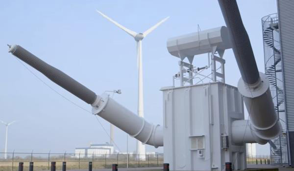
H) Windmill Transformers
We have captured the market entirely by offering the finest class of Windmill Transformers. Across the globe our product is widely appreciated for its high end performance. We offer the Windmill Transformers as per the clients’ specifications. We always deliver within the given time frame at extremely affordable prices.
| Features |
|
| Applications |
|
Applicable standards
IEC / ANSI /BS / IS / SABS/ CENELEC / GOST
Salient Features
- Industry leading ‘Mean time between failure rate (MTBF)’
- The complete customer service package (from quotation to Commissioning)
- One global approach - bringing consistency, delivery performance and technology
- Compact design to meet transportation limits, including the possibility of lay down transportation.
- Modern manufacturing techniques ensuring quality of product
- Robust build designed to withstand electric impulses, thermal and dynamic stress
- Trouble free performance
- Customized design and specification demands
- Customized solution to meet every contingency
- Design technology eliminates the risk of a hot spot
- Outstanding thermal performance resulting from directed oil flow, minimization of losses and control of the hot spot
- Robust design to take care of frequent short circuits
- Excellent process of shrinkage and drying of coils resulting in a sturdy construction